

In the morning, soon after I wake up and start preparing my espresso, I often forget to check the water in my Rancilio Silvia espresso machine. As a result, many shots have been ruined by pressing the espresso button because I forgot to first check if the water tank was almost empty. Therefore, adding a water sensor to my Rancilio Silvia espresso machine has always been a high priority. It has taken some time, but after a few design iterations, I’m very happy with the results. Now I never have to remember to check the water, the machine does it for me. If the water is too low, it lets me know and does not pull the shot. It also is accurate enough to dispense my desired espresso shot volume. In this blog we will describe how to build and install an accurate water sensor for the Rancilio Silvia espresso machine. This is an expansion of the last blog where we described an Espresso Maker That Knows When You Want Some. The water sensor monitors the water tank level and is accurate enough to provide an volumetric espresso shot dispenser. The sensor in the Rancilio Silvia tank has a measurement range of 1700 ml of water with less than 12mL (+5/-7ml) of error. This is an open source hardware and software project. In addition, for those that want a simpler path or just need support, we also offer the complete sensor in our surfncircuits surf shop.
Using Magnetic Waves to Detect Water Levels
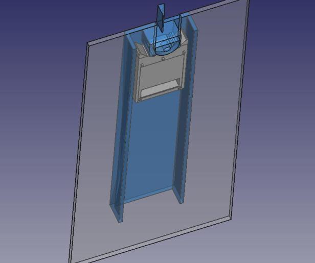
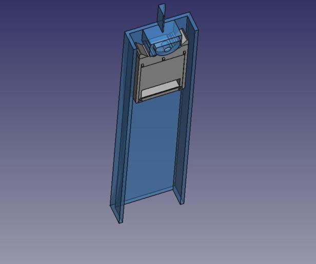
This linear sensor uses inductive position sensing to accurately detect a metal float. The sensor itself is a printed circuit board (PCB) mounted on the outside of the water tank and does not get wet from the water. Check out the actual sensor and 3D drawing in the picture below.


This sensor generates a magnetic field with the use of the LX3302AQPW-EASY sensor IC. A float, which is approximately 6-7mm away from sensor and inside the water tank disturbs the magnetic field and is detectable by the sensor IC. The sensor’s LX3302AQPW-EASY IC reads the voltage of two PCB coils and calculates the position. The ratio of the two receive coil voltages is a 1 to 1 relationship to the position of the float’s position which is guided by the float track submerged in the water. This video shows an overview of the technology. The information of the sensor is communicated to the Raspberry Pi or a microcontroller using the SENT protocol as described in a previous surfncircuits blog.

Sensor Fits on Side of Rancilio Silvia Water Tank
The goal was to design a sensor that would not need modification of the water tank. As a result, the float track hangs on the side of the tank by fitting into the existing tank cutout. The images below show the sensor attached to the tank wall. In addition, the PCB and PCB cover are thin enough so the tank can be taken in and out of the machine if required. The PCB, the PCB cover, and float track are all attached to the side of the tank with a M3x5mm flat head screw.


At the bottom of the sensor a small piece of tape is used to keep the sensor vertical when placing the water tank into the espresso machine.

Adding the Brass Insert for the Screw
3D printed plastic cases can use screws for assembly by using matching brass inserts. The 3D case is design to use a brass insert. To install the brass insert, use an soldering iron to heat up the brass insert which will melt the plastic as it is inserted by putting the soldering tip through it. Then gently push narrow end of the brass insert into the plastic hole until it is flush with the surface of the plastic. Be careful not to push in too far and remove the soldering iron as soon as possible so the plastic does not melt too much. You want the plastic just soft enough to gently push in the insert.

Adding Metal to the Float
Metal itself doesn’t float, but air and the 3D printed PET-G plastic float will. Copper tape, metal weights and epoxy are added to the plastic float for a smooth float operation within the PET-G plastic 3D float track. Copper tape is taped to both sides covering most of the plastic as shown so that the float is balanced. Then small pieces of metal are glued to the opening using food safe RTV silicon so that the floats will be weighted properly while floating. I used M3x5mm flat head screws for these metal weights Afterwards a very thin coat of food safe epoxy is used to coat the plastic to keep it water tight. The 3D printing process does make the inside of the float hallow with air, but it may not be air tight. Some air is required inside float to counteract the copper tape density and if the walls are not thick enough the plastic float will not be air tight. During the design phase, density calculations with respect to water were made to ensure a good balance was possible with approximately 2mm thickness walls. However, by keeping the walls relatively thin and using epoxy a good result were also obtained. In a production environment, the copper tape can be replaced with thin stainless steel, the screws can be replaced with a stainless steel metal slug, and thick enough walls can eliminate the epoxy coating.

Sensor Offset Adjustment and Calibration
The accuracy of the sensor is improved with a PCB sensor offset correction and LX3302AQPW-EASY calibration. A new step by step procedure to calibrate the linear position water sensor for the Rancilio Silvia are described below. The offset adjust is made first with no target and then using a test jig to collect sensor data for additional offset correction. The final step is to use the machine to perform a velocity calibration correction to eliminate additional errors. For the complete steps below, it will be recommended to have a Microchip LXM9518 IPCE programmer in order to monitor and collect sensor data from the LX3302A IC. To make it easier, you can also eliminate all the steps by purchasing the fully assembled and calibrated PCB from the surfncircuits surf shop.
A summary of the steps are as follows:
- Step1: use copper tape to correct the Gross sensor offset error.
- Step 2: Program LX3302AQPW-EASY with given calibration parameters
- Step 3: Install Sensor in Machine and perform velocity calibration
Step 1: A Unique Linear Sensor Offset Correction using copper tape
For the best accuracy, linear and rotational sensors need an offset adjustment for best accuracy. In the sensor, the two receive coils labeled sin and cos, will output a voltage as function of position. The offset error occurs when the signals have a constant non-zero offset voltage.

The offset adjustment is performed so that when no target is near, the two receive coils labeled the sin and cosine traces attached to Cl1 and Cl2 pins on the sensor IC are very close to zero. Normally this offset can be done with just the LX3302AQPW’s internal calibration parameters. Unfortunately, the offset of the Linear Sensor Rev 4 was too much to apply normal LX3302A dynamic calibration. However, a new offset correction using copper tape was used to eliminate the need to iterate the PCB design. Offset correction is important for linear sensors because there is an inherent offset due to the non-symmetrical magnetic fields at the extreme ends of the sensor.
A first order approximation of this offset can be determined when no target is available. Under this condition, the two receive coils are originally designed to receive zero volts. Any deviation from zero volts is a good first approximation of the sensor offset. For the water sensor, the built in PCB offset adjustment was shorted as shown in image below but this was not effective enough to bring the offset voltage to zero.

Then with the complete sensor placed 11mm above a metal surface, two pieces off copper were placed at each end of the PCB until the offset voltage was close to zero voltage. The metal surface represents the metal of the espresso machine cover when the sensor is installed inside a machine. The detection of the voltage can be done with an oscilloscope and placing the two pieces of tape to minimize CL1 and CL2 peak to peak voltage. Alternatively, connecting the sensor to the LXM9518 programmer, monitor the Raw sin and Raw Cos signals so they are as close to 4096 as possible will also work. This video shows how to monitor the raw sine and raw cosine signals.

Step 2: Program the IC with the dynamic parameters
With the gross offset calibration corrected by the copper tape method, the sensor is programmed with the EEPROM calibration file using the IPCE programmer to set the dynamic calibration parameters. These parameters were chosen by using a test jig that represents the metal structure around the sensor, taking measurement date with 6mm and 8mm target air gaps, calculating the best dynamic calibration parameters using the IPCE software. The detail of these steps will be outlined in a future blog, but they are all collected together in the calibration file named LinearSensorRev4EEPROM6mm-24uSENT-IO2.txt located in open source hardware download. This file is used to program the IC with the IPCE and LXM9518 using the LOAD EEPROM from file and Program eeprom to chip buttons in the IPCE software. The EEPROM calibration file also adjusts the SENT output tick time to 24us and the sample time to 250Hz in order to reduce load on the Raspberry Pi.
Step 3: Velocity calibration eliminates machine errors
Velocity calibration is performed to calibrate out any residual errors in the machine and target that may be different from the prototype system. The process samples and saves the sensor output as the water pump empties a full water tank. With the assumption the flow is a constant velocity, the precise water measurement reference is obtained and a calibration file can be calculated to correct error anywhere along the measurement range. This will provide a very accurate sensor needed for automatic shot volume dispensing. The plot below shows the corrected error improvement obtained by using this approach. The maximum error is approximately +5/-7ml over the 1700 ml measurement range.

Eventually the Espresso Connect web software will have an step by step process to accomplish this velocity calibration. However for now, the following steps are needed to be followed to make it work.
Step 3.1: turn off linear calibration
In the step we will be setting up the software so that it uses the sensors output directly without any correction. Inside the EspressoState.py and the getNextState function, call the getWaterLevel method with the optional raw parameter equal to True:
def getNextState(self,clientMsg):
        # this is where the statemachine resides and all the logic between
        # the client Msg is a JSON object that we can read
        global switcher
        # update the temperature and Water Level info and check if error:
        ReadError = False
        # if the control loop is off then capture the temp hear
        if self.STOP == True:
            Temp = self.dev.to_fahrenheit()
            logger.debug("The TEmperature is {:5f}".format(Temp))
            self.updateTemp(Temp)
        waterLevel, oscLevel, ReadError = self.WaterSensor.getWaterLevel(self.EspState["WaterLevel"],
                self.EspState["OscLevel"], True)
        # we will ignore bad water data
        if ReadError == False:
            self.EspState["WaterLevel"] = waterLevel
            self.EspState["OscLevel"] = oscLevel
Step 3.2: Adjust the espresso shot time and volume parameters
Within the Espresso Connect software Brew tap, adjust the maximum shot time to 360 seconds and the shot amount to 2000mL. This will allow a full tank to be dispensed.

Step 3.3: Pull a complete water tank of water
Now place a large cup under the portafilter and have a second cup standing by and press the espresso button on the machine to pull a shot. For this step, an empty portafilter should be used. You will need to switch cups and dump the one that is full as they fill, but do not turn off the espresso button. When the complete tank has been emptied, the water sensor will detect that the tank is empty and turn off.
Step 3.4: Update the CalSampleRaw.csv File
Use the last two rows data collected in the ShotSamples.csv file and copy to the CalSamplesRaw.csv file rows 8-9. When a shot is two rows of data are collected. The calibration will use the fourth set of data which is shown in rows 8-9. Save the file in the CSV format.


Step 3.5: Enable the software to use the calibration file
In the getWaterLevel method, replace True with False.
def getNextState(self,clientMsg):
        # this is where the statemachine resides and all the logic between
        # the client Msg is a JSON object that we can read
        global switcher
        # update the temperature and Water Level info and check if error:
        ReadError = False
        # if the control loop is off then capture the temp hear
        if self.STOP == True:
            Temp = self.dev.to_fahrenheit()
            logger.debug("The TEmperature is {:5f}".format(Temp))
            self.updateTemp(Temp)
        waterLevel, oscLevel, ReadError = self.WaterSensor.getWaterLevel(self.EspState["WaterLevel"],
                self.EspState["OscLevel"], False)
        # we will ignore bad water data
        if ReadError == False:
            self.EspState["WaterLevel"] = waterLevel
            self.EspState["OscLevel"] = oscLevel
Download the complete project
As described in the last blog, the sensor can be read by the raspberry pi zero without the use of another microcontroller. The position sensor is attached via GPIO controlled SENT bus. All the latest updated sensor and 3D printed float, track and cover files are part of the Espresso Connect Hardware and 3D case Design Files download. The list below provides link to this file. Please subscribe to gain access to these files. It is Free and you will be informed of future upgrades!
- Espresso Connect Hardware and 3D case Design Files :Free Subscription Needed
- 3D printed Water Sensor Float,Track, and Cover: /CaseDesign/WaterSensorRev6.FCStd
- PCB Sensor Design: /Gerbers/LinearSensorRev4-5121 is the latest sensor at the time of the blog
- EEPROM File: /WaterSensorRev4/LinearSensorRev4EEPROM6mm-24uSENT-IO2.txt
- Espresso Connect Control and Web Application: Free Subscription Needed
- Espresso State Function: EspressoState.py
- Shot Data File: ShotSamples.csv
- Calibration File: CalSamplesRaw.csv
If you have any questions or comments please ask away in the comments below. I always like hearing from my readers. The water is cold, but the surf has been really nice so far this winter. More to come…

Rancilio Silvia Espresso Maker Water Tank Sensor

Additional References
- Introduction to Inductive Position Sensors
- Microchip Inductive Position Sensor Videos
- Microchip LXM9518 programmer
- Microchip IPCE Software
- M3x5mm Flat Head Screws
- Epoxy to coat float
- Silicon to attach weights to float

Thank you Mark! I was wondering how this was going just this week. I shall enjoy reading it and maybe I’ll even get a chance to make it. Did you send it to Hackaday?
Thanks Kevin for the comments,
I’ll send to Hackaday this week. 🙂
Creative solution!